SerialControl is a simple open source ( GPL2) firmware for the Arduino platform, that allows to remote control Arduinos over a serial connection. The implemented protocol can be used in a XBee peer2peer network. Shark Week For. Multiple Arduino modules can be addressed by an ID. The firmware wraps most IO commands of the Arduino language to make the output pins controllable through a serially attached computer. Download (there is a download link in the source/master tabs) git://github.
All Arduino boards have at least one serial port. Thus, if you use these functions, you cannot also use pins 0 and 1 for digital input or output. Vlc Media Player For Nokia C5-03. Information is passed back & forth between the computer and Arduino by, essentially, setting a pin high. Println's and looking at the Serial Monitor output to.
How can I digitalRead a pin that is in pinMode OUTPUT? Can not get current output pin state on Arduino Due. Digital Pins. The pins on the Arduino can be. While the title of this document refers to digital pins. And an output pin that is left in a HIGH state.

Com/UrsusExplorans/ SerialControl.git Installing To install SerialControl, just copy the source code directory 'serialControl' into your sketchbook folder. Open the Arduino programming environment and load the serialControl package. Adjust the 'ownID' variable to your needs. This variable should be unique on the Arduinos, you want to address. Now the firmware can be compiled and transferred to the Arduino.
Keep in mind that SerialControl requires the 'String library' () to be installed. Usage After installing the firmware on your Arduinos, you can use it by transmitting commands over a serial connection (e.g. Wired or XBee).
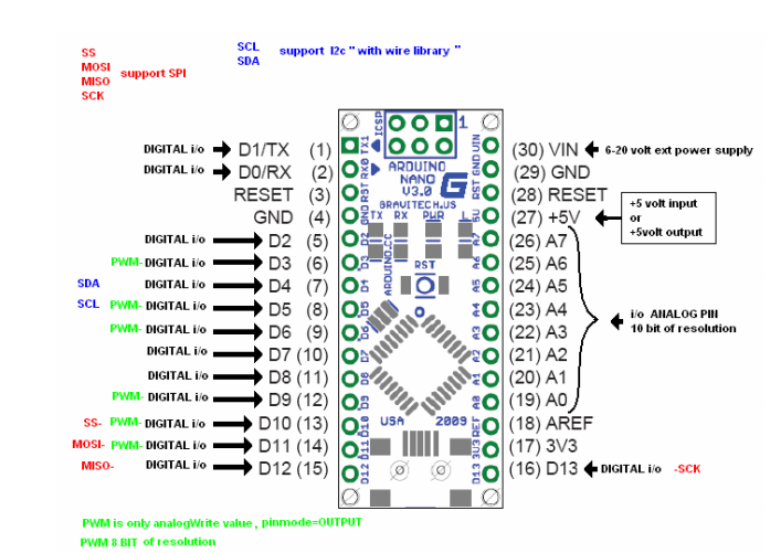
For first experiments you can use the terminal, built into the Arduino programming environment. • The following command lights up the LED at pin 13 of the Arduino module with ID 0: • * 00dw0013HIGH; • To switch it off again, transmit: • * 00dw0013 LOW; • The following command resets all pins to low: • * 00al LOW; As you might see, the commands have all the same structure: • The first two characters determine the ID of the desired Arduino module. • The third and the fourth characters shape the command: • pm: wraps the pinMode function • dw: wraps the digitalWrite function • aw: wraps the analogWrite function • al: 'All' is a convenience function to change the mode of all output pins • characters 5 to 8 form the first argument • characters 9 to 12 form the second argument • if the arguments have less than 4 characters, the leading positions are white spaces. • finally every command string is finalized by a colon character (;). Known Issues • So far it is not possible to read out input pins.
• For performances in combination with XBee modules: • Only Series 1 types work in real-time. The mesh algorithm of the Series 2 slows the transmission down quite much. • The firmware does not cope with transmission collisions, so it can be beneficial to repeat transmissions in short periods. Misc • Blog entry: • Arduino forum thread.